UncategorizedVauxhall/Opel Corsa B heating control panel lights servicing

Vauxhall/Opel Corsa B heating control panel lights servicing

When I first got my car I was a bit surprised for not having any illumination of the heating controls, which can be a problem especially in the Winter, when the days are short and you need to use these controls a lot more!

Anyway, there is illumination indeed, the issue here is that the lighting is designed to stay on regardless of whatever setting you may have on your outside lights. Add to it incandescent bulbs and a horrible procedure to extract them from the panel (more on that later) and no wonder most old Corsas lying around have no functioning lights any more – the owners are coping with it the best way they know, either by turning on the courtesy light or simply by memorising the position of the controls.

Not for me, though! 🙂 – I hate knowing something could be working but it isn’t, but at the same time I hate forking out money on seemingly “little” things (and Vauxhall charges £50+ for the “privilege” of sorting these lights for you!). Hence, armed with some LEDs I got from eBay, my Haynes manual and a few more bits and pieces, I set on trying to sort this out.

Firstly, here is the part in question which holds the lights in place. It definitely doesn’t look familiar to anyone owning one of these cars, as it is buried deep into the fascia:

2014-04-11 14.03.28

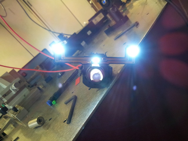
Or, as it sits in the fascia (I took the previous photo as I was testing the lights hooking the part to a 12 V DC power supply),

2014-04-12 14.52.51

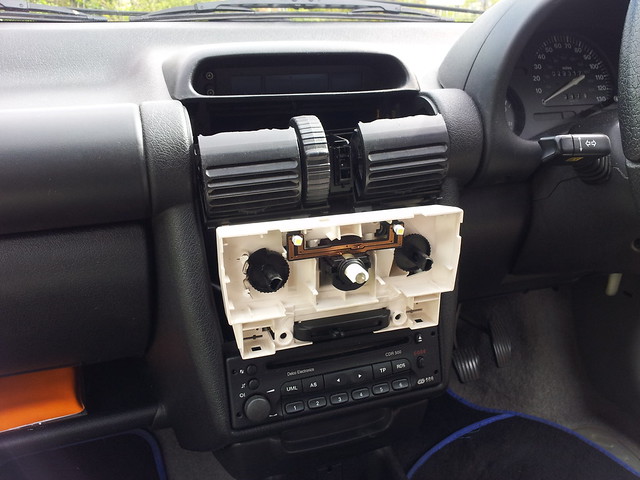
To access this holder all you have to do is follow the instructions from the Haynes manual: pushing the vents down to reveal the screws behind them, which will in turn release the multi-function display on top; and after removing the air recirculation switch and the knobs you can finally get to the lights.

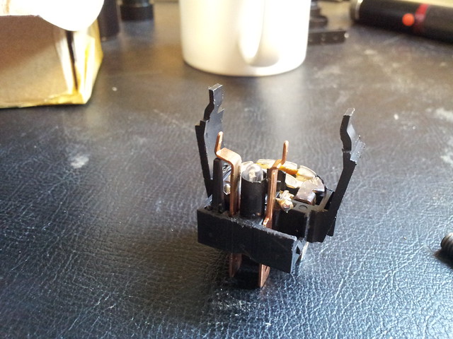
Unfortunately there is something the Haynes manual misses – of these three bulbs only two of them are socketed, given that GM changed the design of this holder in ’97 and with that the central bulb became soldered inside the central switch (the one that controls the fan and the demister). Hence, I had to pry it open in order to get to the bulb,

2014-04-11 09.49.13

thus separating it from the remaining bulbs, which sit on those two arms:

2014-04-11 09.49.32

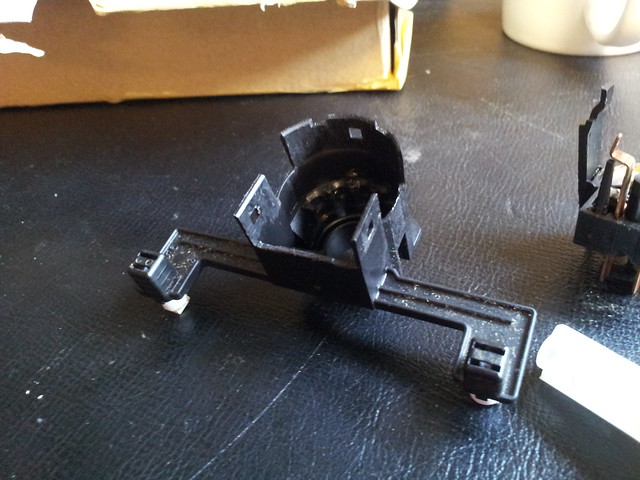
Given that I had intended to replace these lights with LEDs in order to avoid going through this procedure all over again in a year or two’s time, I had to be careful with the polarity. The pins on the back of the assembly are labelled as far as I remember, one of them having a plus sign, hence you can always test with a DC power supply before you take apart half of the car to replace the lights.

My advice – given that you will necessarily have to pry the fan/demister switch open to replace the light, get a used one off eBay or a scrapyard (they should be cheap…) and work on that one – in this way you can just replace the whole unit and be sure it effectively works correctly.

That’s it, folks! Hope you’ve enjoyed the tutorial, I felt I should do one as I kind of missed one when I attempted to do this myself (there were a few images in an enthusiast forum, but they have since been removed…). Any questions, please do ask!

Categories: Uncategorized Tags: , , , , ,

Comments

  1. Anthony of Sydney NSW

    July 12, 2015 12:38

    Dear Manuel, I have exact model where the conducting tracks are located at the front of the panel reference your first photo. Two questions please with the first question leading to the second. (1) When you switch on the headlights, there is supposed to be 12V on the Cu tracks. Using a multimeter, there is 0. This suggests that there is an open circuit. Other evidence, regardless of the polarity of the LED it should light up on one of the LED's orientations. It looks like that I may need to do the same as what you did in order to not only replace the centre light, but to also replace the air-conditioning light left bulb and repair the open circuit. (2) In your above tutorial how did you (a) pry it out from the main fascia - that is get from photo 2 to photo 3 and (b) from photo 3 and photo 4 to photo 1? I'm not sure what these parts are. I have copied the extra photos from flickr, but still don't know what you did to pry it out. Note I have the copy of the Haynes manual. Do I still have to 'draw out' the whole heater unit out - that is disconnect the connecting cables in order to pry out the parts you pried out? Please excuse my lack of 'mechanical ability'. Many thanks for a possible answer. Anthony, Sydney NSW
    1. Anthony of Sydney NSW

      July 13, 2015 07:36

      For some reason the Cu tracks are shorted. Tested each track for conductivity between ground (the car chassis) and the particular track. Both shorted to ground. Still have not figured out how to pry the Cu track/lamp holder from the heater unit.
      1. July 13, 2015 08:36

        Hi Anthony! I don't recall 100% the procedure as I did it over a year ago now, but I remember the removal was a lot of trouble!! The Haynes manual only takes you to the part where you have the whole mount still attached to the fascia (Fig 2), because they haven't bothered updating it to the later revision where you cannot simply upgrade the bulb in the central knob (the one with the de-mister switch). The other two are easy as they are socketed, it is just a matter of removing and replacing with LEDs - and you can test the polarity by turning the key in the ignition as they come on regardless of the outside headlight setting (that's why the incadescent bulbs were dead in the first place!). You should see 12V between the two tracks leading to each of the sockets. As for the demister switch, I think it is just held in place by the connector behind it (but I cannot be sure as I did it a while back). This should remove everything, ie what you see in the first figure. But to get to the bulb in there you'll have to pry those plastic tabs to separate the part with the connections from the plastic casing (which also contains the copper tracks). That little white rod should also come out! I'm sorry I can't be of greater help, I should have taken more photos, I guess! HTH, -MM
        1. Anthony of Sydney NSW

          July 31, 2015 03:24

          This is a progress note about the heater panel. It is best to to remove all the cables for vent air redirection, temperature and external/internal air circulation, as well as the electrical connections! It is beneficial as you follow on. In my earlier note, I have found the source of the short circuit on the Cu tracks to be from globe inside the demister switch. This was cleared and replaced with a new LED, but not as you know it. I did not think that replacing the globe with a simple LED is strong enough. I used three SMDs on a PCB with a suitable load resistor (by Ohm's law) and hard wired (there's no socket) and mounted the PCB on the shaft formerly occupied by the filament globe. Works! For those who did not know, Corsa models (or for those in Australia, the Holden SB Barina) equipped with an air conditioner, there is a fourth lamp located behind the panel. In a similar method of distributing light to the top of the switch, as with the demister switch, the light from the lamp is guided through the shaft to the front button. I originally replaced the filament lamp with a T5 three smd LED lamp. BUT none of the smd LEDs faced the 'light guide' shaft resulting in very little light delivered to the end of the shaft to the button. I made my own T5 lamp with 3 smd LEDs with a loading resistor (due to Ohm's law) on a PCB with the LEDS facing the light guide shaft while mounted on a T5 plug. The air conditioner never 'shone' like that before! Another note on front panel LEDs. Don't use T5 SMD on PCB where the PCB also acts as the plug. This is because each contact on the front panel lamps will make contact with the +ve and -ve electrodes of the PCB led. The result is a short circuit. Therefore use a T5 plug with one electrode per side. HOWEVER, T5 smd PCB lamps will work with the air conditioner, provided that the LEDs face the light guide shaft. Such lamps will also work with the multifunction display (MFD) (time, date, temperature, radio - frequency, volume, treble, bass). Wanted to contribute something to complement this forum, now want to close this topic. I thank Manuel for providing another insight into the mysteries of Corsa (Holden SB Barina) heater panel. Regards Anthony of Sydney NSW
          1. August 23, 2015 12:55

            Brilliant! Thanks Anthony, glad to hear that you've managed to work it out. I will probably have to go back to these instructions fairly soonish as the cheap LEDs I got off eBay started failing - they do have the PCB in the socket, but with one electrode per side so they don't short-circuit; there seems to be a loose connection somewhere as they power on and off erratically, especially the one that had to be soldered!. Thanks again, Manuel
  2. Anthony of Sydney NSW

    September 19, 2015 22:56

    Dear Manuel, Three points on the LEDs used for the front panel. (1) On LED mounted on PCB also acting as a plug. If you have two electrodes per plug, you can "scratch" off the unwanted conductor on each side. BUT be very careful when "scratching" off the unwanted conductor, your set of LEDs may partially operate. That is, for example the +ve electrode on one side of the PCB 'plug' may not trace the same way as the +ve electrode on the on the other side. In the case of having two electrodes per side of a T5 LED: Your best bet is to get an ohmmeter and trace out the circuit of all the LEDs on the T5 LED. The benefit of doing this is in case one of the LEDs in the T5 LED don't operate, you can solder a wire to the point of where much more than the electrode was removed. (2) Is there enough light from the LED to light up the panel? Two issues (i) not enough light, and (ii) what if you are so fussy that the "red" section of the temperature controller cannot be seen because blue's λ will be filtered out by red section. (i) Not enough light on air conditioning panel. Assuming that you are satisfied with the light from both the air conditioning and demister switches, you may find that the "dials" are not satisfactorily lit. You could use an LED strip. You can buy a roll up to 5m which may cost anywhere between $12 (Australia) to $35 (Australia) on ebay, or you can purchase a smaller strip. For example, you could use a smaller strip which is marketed as a footwell LED for $2.34 (Australia) on ebay. NOTE this is not the only vendor of the LED footwell strip, but this is an example, http://www.ebay.com.au/itm/60CM-60-SMD-Car-Strip-Under-Light-Neon-Footwell-Flexible-Blue-WS-/221784482460?hash=item33a362a29c. NOTE 2: Both strip or footwell lights have three LEDs and a load resistor (180ohm) per section. It may be tedious and time-consuming stripping to sections of three and/or fashioning the position of the LEDs to sit directly underneath the translucent sections of the dial. NOTE 3: This gets even more tedious when fitting the LEDs for the numbers on the fan switch middle and the air redirection switch on the right. Fitting a section with its plastic encasing will give an unsatisfactory result. You may need to break down further the three LED section NOTE 4: Where fitting on the air direction switch, located on the right, and the numbered sections for the fan speed switch, the middle control, you may need to even strip the section with 3 LEDs further to its individual LED components and load resistor in order to position these LEDs under the translucent sections of the dial. (ii) What about the red section of the temperature control switch on the left? If you are using a blue LED as a source, basic science says that a if you filter other than blue is placed in its way, you will not see the blue light because red's λ is different to blue's λ . But you want to see the "red" section illuminated. Solution either place directly under the red section a set of three red LEDs or three white LEDs with a suitable load resistor (due to Ohm's law) under the red. NOTE 1: It may be tedious here because if you use at the top of the temperature controller blue LEDs, you may need to make from individual blue LEDs closely grouped since the strips are spaced wider than the space required for fitting the blue LED at the top of the temperature control switch. NOTE 2: You will have to purchase three RED or WHITE LEDs with a suitable mounting to mount directly underneath the red section.' Notes for (2) (i) and (2)(ii): * This is not the only way to lighten up the dials of the Corsa B or Barina SB (Australia) air conditioning. If you search the web, you will find that some people have used aquarium leds to fit around the panel. * There may well be better and less tedious methods than mine for lighting the air conditioning dials of the Corsa B = Barina SB. The tediousness comes from (a) stripping the LED strips by removing the SMD components and by "making" a contact point for the 12V connection. and (b) the tediousness also comes from making sections to fit in the numbered sections of the fan speed control, middle nd the air direction controls, right as well as the top part of the temperature control, left. * Method of stripping the LED smd components. Fortunate not to have been injured when separating protective cover of strip from the LED and/or load resistor. * I have done it, it does work, but found the job rather tedious. However, I was happy with the result. (3) What if you are not fussed by the colour of LED? Use white LEDs, and in the sockets noting the the number of electrodes on each side of the PCB plug, as in (1). Though I have not tested with white LED globes, simple one-LED globes may not give satisfactory result. You may want to try T5 with 5 LEDs, with three on the top (say) and two on the bottom. Be mindful of the direction of the bottom LEDs and as noted earlier in (3) and in (1) the number of electrodes on each side. Hope this helps. Anthony of Sydney NSW

Reply to Anthony of Sydney NSW cancel

Your email address will not be published. Required fields are marked *